Tuesday, September 26, 2006

Layer States

Named layer states allow you to quickly restore saved Layer settings. Access the Layer States Manager dialog from the Layer dialog.

Click the New... button, to create a named "snapshot" of all the current layer settings. This snapshot includes the current viewport layer visibility status.

Use the Restore button to restore the desired settings of the selected named layer state. Check on the layer properties you wish to restore from the selected saved layer state. You can turn off layers not found in layer state to ensure that layers added after the layer state was saved are not displayed, giving you the exact look of the drawing when the layer state was created.

Layer states are stored within the drawing but can be exported for use in other drawings. Note that Xref layers are also saved in layer states. Xref layers have the name form:

xref_name¦layer_name

Because the reference name is part of the layer name, fully restoring layer states from one drawing to another is possible only if they share identical references.

Quick Note on this Tip:

WARNING! Extreme Techno-Babble.

The AutoCAD Express Tool LMAN (Layer Manager) introduced back in Release 14 has heretofore been the method for saving layer states. This tool, while still part of the Express Tools package, is obsolete and it is recommended that it not be used. Use the layer states built into the AutoCAD Layer command instead. The technical reason for this is in the efficiency and reliability of the underlying code. The new layer states are stored as discreet entries in a dictionary (non-graphical object). The old LMAN layer states are stored as extended entity data attached to the Layers. This can make purging layers impossible until first deleting the saved layer states and purging the LMAN application (RAK).

Tuesday, September 19, 2006

Drag-and-Drop

Windows drag-and-drop functionality can be used in AutoCAD with several file types. Open AutoCAD and Windows Explorer and tile them so that you can see both applications on your screen. Locate a file in Explorer, click and hold the mouse button down as you drag it into the AutoCAD drawing editor. The behavior of this operation varies depending on the file type you are dragging into your drawing. In the example above, dragging a text file (.txt) yields an Mtext entity. Dragging an Excel Spreadsheet (.xls) or Word Document (.doc) will place an OLE object.

You can also drag entities from drawing to drawing (or from application to drawing). Tile or Cascade your open drawing windows in AutoCAD. Select an entity in one drawing and drag it into the other drawing.

Dragging with the right-click gives you a context menu when you drop the file or entity. For example, if you right-click drag a drawing file (.dwg) from Explorer, you can choose to Insert as block, Open, Xref, or Create a Hyperlink to the file.

The chart below shows some file types germane to AutoCAD and the results of drag-and-drop.

File Type Left-click Drag Right-click Drag
.DWG, .DWS, .DWT Insert Insert, Open, Xref, Create Hyperlink
Note: Xref only works for DWGs
.TXT Mtext
.DST Opens Sheet Set
.SCR Runs Script
.LSP Loads LISP file
Image files:
.JPG, .CAL, .TIF, etc.
Attaches Image
.DOC, .XLS OLE Move, Copy, Link, Create Hyperlink

Tuesday, September 12, 2006

Divide and Measure

The Divide and Measure commands allow you to place markers along an entity dividing it into a given number of segments or given segment lengths respectively. By default either command places Nodes (Points) along the divided/measured entity.

The example below uses the MEASURE command to place Nodes along a Pline at 5' increments. Setting PDMODE to 3 and PDSIZE to 2 controls the display of the Nodes, in this case making them appear as an X.


Handy? Maybe. But, you can also use a Block for your marker making these commands even more useful.

The following example uses MEASURE to create a sidewalk with joints. Create a Block named SWJT (sidewalk joint) that is a 4' vertical Line with the insertion point at the midpoint. Offset the Pline 2.5' on both sides to create a sidewalk.


Measure the center line of the sidewalk. Use the Block option with the SWJT Block placed at 5' increments.

Command: MEASURE
Select object to measure: [select the Pline]
Specify length of segment or [Block]: B
Enter name of block to insert: SWJT
Align block with object? [Yes/No] : Yes
Specify length of segment: 5

Finally, delete the center line.

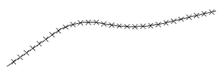
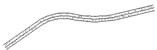
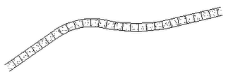
Use this same procedure to quickly create all kinds of repetitive elements: layout parking stripes along a curve, divide an alignment with track lights, place rebar in details, etc.

Bonus Tip: Nodes or Blocks created with either Divide or Measure are placed in the previous selection set. This makes it easy to edit them. For instance, to Erase the Nodes or Blocks just created type ERASE then P for previous to select them.

Tuesday, September 05, 2006

Rotating your View

Have you ever had that horrible experience where someone has rotated your background drawing? The first tenet of shared backgrounds is "Never Move the Background." If you need to view a background drawing in a different orientation, rotate your viewing direction, don't rotate the drawing.

You can rotate your viewing direction in Model Space or from within a Model Space Viewport. Consider the following plan:

The first thing to notice is the UCS Icon in the lower left corner of the Viewport. (If your UCS Icon is not on, let me strongly urge you to consider turning it on via the UCSICON command.) The icon indicates that the current coordinate system is World with Y increasing upwards and X increasing to the right.

Let's rotate the viewing direction to more comfortably view, plot, annotate, or work on the model.

Use the UCS command to create a User Coordinate System aligned with the building. I used the 3-point method to exactly align my UCS with the building.
Command: UCS
Current ucs name: *WORLD*
Enter an option [New/Move/.../Apply/?/World]: 3P
Specify new origin point <0,0,0>: [pick Pt1]
Specify point on positive ... X-axis: [pick Pt2]
Specify point on positive-Y... of the UCS XY plane:
[pick Pt3]
Notice the UCS Icon and crosshairs are now aligned with the building.

Once the User Coordinate System is established, use the PLAN command to view this UCS in Plan view (i.e. with Y up and X to the Dexter.) You'll have to rescale the Viewport afterwards as PLAN always Zooms to Extents.

You can leave the UCS set, or return to World coordinates, depending on your needs.

Alternate Method: The old DVIEW command with the Twist option will rotate the viewing direction without rescaling the Viewport, but you must know the rotation value because you cannot "show" it to the DVIEW command by picking points.