Non-Rectangular Viewports
Use the MVIEW Polygonal and Object features to create non-rectangular viewports. Viewports can be created from any closed AutoCAD object. The easiest way to access these options is by using my favorite new toolbar, the Viewports toolbar.
 Let's quickly walk through each of the buttons on this toolbar. Ignore the first button, it merely brings up the Viewport dialog. The second button creates a normal rectangular Viewport. Button three lets you draw a non-rectangular Viewport, similar to drawing a Pline. The fourth button converts an existing closed object (circle, pline, etc.) to a Viewport. The last button is similar in that it lets you clip an existing rectangular Viewport against a closed object. The drop down list at the end of the toolbar lets you easily scale your Viewport to common zoom scale factors. It either scales the active Viewport or the selected Viewport. You can type in your own zoom scale factors if they're not in the drop down list; e.g. 1:60.
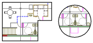
Use the Polygonal Viewport button and the Convert Object button to create the following non-rectangular Viewports. The Polygonal one is drawn. The circular one is a Circle that is selected for conversion to a Viewport.
 If you LIST either of these Viewports, you see that they are a unique element; they're both a Polyline or Circle and a Viewport. Because they are also AutoCAD objects, they can be edited just like objects. You can PEDIT the Pline Viewport, and grip edit both objects.
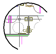
But what else can you do to these objects? Draw a Line across the circular Viewport and using the TRIM command, select the Line as your trim boundary, trim the Circle, then erase the Line.
 The result is a Viewport from an Arc. Friends, one ought not be allowed to do this! You cannot select an Arc to convert to a Viewport, so why should AutoCAD allow you to trim a Circle bound to a Viewport? That's just asking for trouble.
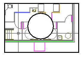
A Bonus exercise for the reader: see if you can figure out how to achieve this Viewport:
 This is a single viewport with a circular void in it; see how the crosshairs pass behind the circular region?


11 Comments:
What version is this new viewport toolbar in? I am working in 2006 and cannot seem to find it.
~Thanks
Yes, it's in ACAD 2006 in the default ACAD.CUI.
The easiest way to display it is to right-click on any toolbar to display a list of available toolbars, then select Viewports from the list.
You can also right-click in a blank area where the toolbars are docked which displays a list of loaded menus, select the ACAD menu, then Viewports.
use a rectangle and a circle. Convert to region and subtract the circle from the rectangle. convert to a paperspace viewport. time to complete was 28 seconds. :-)
joe
Awesome! You did it. Now, did you include the time it took you to come up with this method in the 28 seconds? :-)
Hi im working in autocad 2007 and my viewport toolbar doesn´t have the last to icons, how do i get them? if i type MVIEW command I don´t have any Object opption, plz help im going nutz!
Just a guess, but perhaps you're working in a custom environment and someone has redefined your MVIEW command?
Try this, type .MVIEW at the command line (that's MVIEW preceded by a dot); see if that gives you MVIEW with the Object option.
All of you not finding the commands on the Viewports toolbar:
You probably have the LT version of Autocad (Limited). Just create the viewports in a full version Autocad, then you can use them in LT as well.
Cheers
hi.
I'm working with AUTOCAD 2010.when i try to pint my viewport comes as a blak rectangle. does anyone know why?
That's it. The Light version does not have it. I was getting crazy.
Thanks you very much
I have same problem as mentioned above by joearch i.e. Can anyone tell me why and what to do when, whenever I create a non rectangular viewport and print the file to PDF, it fails to print half the dwg? It's fine when being sent to a plotter.None of the solutions provided above solve my problem.Can you help telling how this could be
Post a Comment
Subscribe to Post Comments [Atom]
<< Home