Divide and Measure
The Divide and Measure commands allow you to place markers along an entity dividing it into a given number of segments or given segment lengths respectively. By default either command places Nodes (Points) along the divided/measured entity.
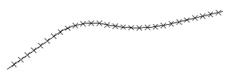
The example below uses the MEASURE command to place Nodes along a Pline at 5' increments. Setting PDMODE to 3 and PDSIZE to 2 controls the display of the Nodes, in this case making them appear as an X.
Handy? Maybe. But, you can also use a Block for your marker making these commands even more useful.
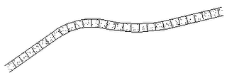
The following example uses MEASURE to create a sidewalk with joints. Create a Block named SWJT (sidewalk joint) that is a 4' vertical Line with the insertion point at the midpoint. Offset the Pline 2.5' on both sides to create a sidewalk.
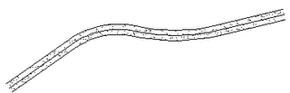
Measure the center line of the sidewalk. Use the Block option with the SWJT Block placed at 5' increments.
Command: MEASURE
Select object to measure: [select the Pline]
Specify length of segment or [Block]: B
Enter name of block to insert: SWJT
Align block with object? [Yes/No]
Specify length of segment: 5
Finally, delete the center line.
 Use this same procedure to quickly create all kinds of repetitive elements: layout parking stripes along a curve, divide an alignment with track lights, place rebar in details, etc.
Bonus Tip: Nodes or Blocks created with either Divide or Measure are placed in the previous selection set. This makes it easy to edit them. For instance, to Erase the Nodes or Blocks just created type ERASE then P for previous to select them.
posted by Ward Romberger @ 1:19 PM
1 Comments
![]()
![]()


1 Comments:
Good post.Its now really easy to use Divide and Measure commands to place markers along an entity dividing it into a given number of segments.Also I never knew that to Erase the Nodes or Blocks just created type ERASE then P for previous to select them.
Post a Comment
Subscribe to Post Comments [Atom]
<< Home