Tuesday, March 04, 2008

Edit Multiple Pieces of Mtext

Here's a clever little tip sent in from a user in one of our remote offices.

Select multiple pieces of Mtext and use the Properties Palette to edit the content. Of course entering new content where it says *VARIES* would result in overwriting all selected occurrences, but did you know you can use the ellipsis button to invoke the Mtext editor and edit each selected Mtext entity in turn? Each time you click OK in the Mtext Editor the Editor jumps to the next Mtext in the selection.

Just when you think you know everything...

Thursday, February 21, 2008

Adding a Splash of Color

Have you ever needed to add a splash of color to your otherwise black and white drawing?

Let's say that you have a plan drawing that plots using a CTB pen table where all the layer colors are mapped to black pens, and you need to plot a few lines or hatches in color. Ordinarily I'd advise you to convert the drawing from CTB (color table) to STB (style table), then set all the layers to plot with a black style except for the few that you want in color; those we would plot with the Normal style so that they plot with the layer color. However, whoever created this sheet didn't assign lineweights to their layers so many of the layer lineweights are still Default (i.e. not set) and hence the black line work wouldn't plot correctly.

Here's the tip:

The only colors that map to pens in a CTB drawing are the index colors 1-255. True colors, or Pantone colors, plot as displayed and do not map to CTB pens. So, use true colors for the layers or entities you wish to plot in color.

When you first click over to the True Color tab, you see all the true color information of the current standard index color. Click to select this same color as true color, then click OK.

Notice how the resultant true colors are displayed in the layer dialog. (I'll admit that I cobbled this together from some older existing drawing so ignore the poor layer names.)

Here's a portion of a plot using the TriSrv_F.ctb (Benham's old tried and true A/E/C CADD Standards pen table) and these few true color layers:
We still have the black line work that we normally expect in our plots, but we also have the added benefit of color for a presentation plot or a PDF plot.

Wednesday, January 09, 2008

Intro to Groups

Straw poll: Ever heard of Groups in AutoCAD? Do you use Groups?
Most people are familiar with Blocks where multiple instances of a collection of entities point to a single definition. Editing the geometry of the Block definition modifies the appearance of every instance, or insertion, of the Block.

Similarly a Group is a collection of multiple entities that can be moved, rotated, deleted, etc. as if it were a single entity. However, unlike a Block, each Group is distinct. A Group can be temporarily un-grouped to modify sub-entities.
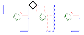


These workstations are composed of individual Blocks for the chair, partitions, and work surfaces. The Blocks were then collected into a Group named WKSTN-L1 using the GROUP command and copied two times.
The copied Groups were subsequently modified to account for site conditions, like the column in the second workstation or the end panel of the first workstation. Using a Block for the workstation wouldn't prove useful, since each workstation is slightly different in configuration, even though it's comprised of the same basic Blocks.
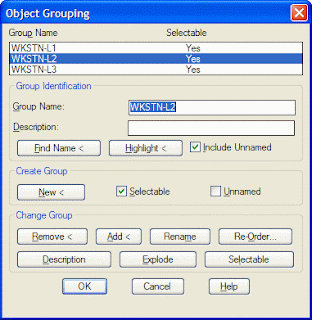


Copying a named Group results in an anonymous, unnamed Group. You can give the unnamed Group a meaningful name in the Object Grouping dialog using the Rename button. Use the Include Unnamed toggle to display the unnamed Groups.
This dialog does all sorts of other useful things:

Use the Highlight button to identify a Group by highlighting it on the screen (see image above).

Use the Find Name button to list the Group name of a selected entity.

Individual entities can be added to or removed from existing Groups using the Add and Remove buttons.

Explode existing Groups to permanently un-Group them and remove the Group name from the drawing.

The PICKSTYLE system variable controls whether a component entity or the entire Group is selected in editing operations. The default setting of PICKSTYLE is 1 (one) which is Group selection. To be able to Move, Copy, Erase, etc. a single entity of a Group, temporarily set PICKSTYLE to 0 (zero). The Ctrl-H key combination is a quick way to toggle PICKSTYLE between 1 and 0. (This is tantamount to using the Group dialog to change a Group's Selectable setting between Yes and No.)

Grip editing always works on component entities regardless of whether the entity is part of a Group or not.

The PICKSTYLE variable does double duty controlling the behavior of Hatches and their Boundaries, but that's material for another Tip another day.

Labels: , ,

Wednesday, December 05, 2007

Delete Duplicates

OVERKILL

Have you ever had a drawing (from an outside source of course) with lines atop lines, or multiple line segments used where a single line would serve? There's an AutoCAD Express Tool to help with cleaning up such drawings. Start the OVERKILL command from pull down:

Express > Modify > Delete Duplicate Objects

The following dialog is displayed (shown with default options):

So what's it do? Primarily it deletes duplicate entities: text on top of text, blocks on top of blocks, lines on top of lines, plines on top of plines, etc. Where there were multiple entities that are exactly the same in size, position, orientation, etc. only one remains after running OVERKILL.

The dialog allows you to set certain comparison options.

  • The Numeric Fuzz - this value specifies how far off the geometry can be and still be considered duplicate. Increase this value if you have multiple lines, blocks, text, etc. almost on top of one another, but just ever so slightly shifted. (Which one is kept is anyone's guess.)
  • All the Ignore toggles tell OVERKILL to treat identical objects as one that may reside on different Layers, have discreet Colors, Linetypes, etc. Use in any desired combination.
    In this example there are two north arrow blocks, one slightly offset from the other. I've changed the color of one of the blocks to red to make it more apparent. Running OVERKILL with the Ignore Color toggle checked, and a fuzz factor greater than the offset, leaves just one north arrow block. Oh look, it's the red one.
  • I recommend unchecking the PLINES optimization, for the first run anyway. This option examines plines for excess vertices and segments that track back upon themselves. It's a powerful and useful option, but it really slows down the comparison process. I'd run it in a subsequent session and limit it to just some of the plines at a time.
    The left Pline shows the original vertices. Run OVERKILL with Pline optimization to obtain the right Pline.
  • The OVERLAP toggle tells OVERKILL to treat co-linear entities as one if they partially overlap.
  • The END to END toggle combines co-linear objects whose endpoints touch (or are within the fuzz factor).

    In this example the top part has lines that overlap, as indicated by the black and red lines, and lines that almost touch. Running OVERKILL with the Ignore Color toggle checked, and a fuzz factor greater than the gap, results in the two lines below.
If you're very brave, and really understand this command and its options, you can even run it against multiple drawings using a script and the command line version, -OVERKILL.
Command: -OVERKILL
Select objects: 2144 found
Select objects:
IGNORE=Color
Fuzz=0.000001, Optimize PLINES=Y, etc...
Enter an option to change
[Ignore/Fuzz/Plines/parTial/Endtoend] <done>:

Hint: You probably want to do this on a copy of the drawings.

Tuesday, November 13, 2007

Here I am to save the day...

SAVEALL (AutoCAD Express Tool)

This command will attempt to save all open drawings (without having to flip through each one), leaving the drawings open for continued editing. If a drawing has not yet been named, you're prompted for a file name.

CLOSEALL (just plain ol' AutoCAD)

All open drawings are closed. A message box is displayed for each unsaved drawing, in which you can save or discard any changes to the drawing before closing it.

QSAVE

Quick Save of the current drawing without prompting for file name, unless the current drawing has no name in which case the SAVEAS dialog is displayed. This is the command that's run when you select SAVE from the File pull down.

SAVEAS

Save the current drawing to another name and change to that drawing.

SAVE

Displays the SAVEAS dialog. Save the drawing as the current name or save as a copy under another name. AutoCAD stays in the current drawing. This command is only available from the keyboard.

There's only a slight variation between SAVE and SAVEAS. Did you spot it?

Wednesday, October 31, 2007

Lines Merge

What's wrong with this picture? These two AutoCAD plots were made with all the same settings: Plotter, pen table, scale, etc. from the same drawing/same layers. However, the first image displays the lighting fixtures as bold and readable, whereas the second image shows the lights as obscured by the ceiling grid.
The only difference between the first and second plot is the order the entities were drawn in the database. In image two, the ceiling grid was placed last (or xreferenced last) and so is on top of the underlying light fixtures.

Can this be controlled? Can we force the light fixtures to show bold? The answer is a qualified yes.

For most plotters the default setting for Merge Control is Lines Overwrite. This means that the last entity placed in the database is plotted on top of other entities. At Benham, we typically change this setting on all of our plot devices to Lines Merge.This allows the bold, solid black light fixtures to "show through" the screened, gray ceiling grid.

Now for the qualification: not all plotter drivers have the Lines Merge ability; the DWG to PDF.pc3 for example does not. So now how does one make sure that the light fixtures plot bold and black when plotting to PDF? You're going to need to ensure that they're on top. Use the DRAWORDER command to send the ceiling grid to the back or bring the lights to the top.

Wednesday, October 17, 2007

The ByBlock Property

Here's a little tip that borders the edge of extreme AutoCAD nerd: the ByBlock property.

First, some background:

The default property for a new entity is the ByLayer property. This applies to the Color, Linetype, Lineweight, and PlotStyle properties. This means that the entity gets these properties from the layer on which it resides. If you move an entity to another layer, it inherits the new layer's properties.

You can override an entity's ByLayer property and give it an explicit value. For example you might select a line and make its color Green regardless of the color of the layer. Consider the following example. In the first image all entities are drawn on Layer A-WALL-FULL which has a Color of 2, Linetype of Continuous, and Lineweight of 0.35mm. The second image shows the same entities when moved to Layer A-WALL-JAMB which is Color 1, Ltype Continuous, and Lineweight 0.25mm. The last image shows what happens when the properties of the line are assigned explicitly.

Lost yet? Let's further complicate this by introducing nested entities, i.e., entities within blocks. If an entity in a block is created on layer 0, it inherits the properties of any layer the block is then inserted on. If the entities in a block are created on any layer other than 0, they retain the properties of that layer. If entities in a block are given explicit properties, they retain those properties regardless of the insertion layer.

And, finally, we come to the reason for this discussion, the ByBlock property! Let's draw some entities on layer 0 and make a block of them. We will leave all the entities of the block with the default ByLayer properties except for one entity. To this entity we assign a Color and Plot Style of ByBlock.

What's happening here? The first image shows the settings of the entities that make up the block. The second image shows this block inserted on layer G-ANNO-TEXT. Note how the entities within the block take on the properties of the layer. In the third image we select the block and change its Color to 8 and its Plot Style to 40 (which is 40% black according to our pen table). Notice that only the upper sweep changed. It was the only entity in the block definition that had a ByBlock property, so it alone took on the properties that we assigned explicitly to the block. The other entities had a ByLayer property and so retained the insertion layer properties. Also notice that the ByBlock property behaves just like ByLayer until you actually assign a property to the block.

All of the Benham title blocks were created to behave in this manner. So, no matter what layer standard or pen table are required by the project, we can still get the Benham logo to plot correctly by changing the properties of the block. There's never need to explode or redefine anything.