Tuesday, August 29, 2006

Non-Rectangular Viewports

Use the MVIEW Polygonal and Object features to create non-rectangular viewports. Viewports can be created from any closed AutoCAD object. The easiest way to access these options is by using my favorite new toolbar, the Viewports toolbar.
Let's quickly walk through each of the buttons on this toolbar. Ignore the first button, it merely brings up the Viewport dialog. The second button creates a normal rectangular Viewport. Button three lets you draw a non-rectangular Viewport, similar to drawing a Pline. The fourth button converts an existing closed object (circle, pline, etc.) to a Viewport. The last button is similar in that it lets you clip an existing rectangular Viewport against a closed object. The drop down list at the end of the toolbar lets you easily scale your Viewport to common zoom scale factors. It either scales the active Viewport or the selected Viewport. You can type in your own zoom scale factors if they're not in the drop down list; e.g. 1:60.

Use the Polygonal Viewport button and the Convert Object button to create the following non-rectangular Viewports. The Polygonal one is drawn. The circular one is a Circle that is selected for conversion to a Viewport.
If you LIST either of these Viewports, you see that they are a unique element; they're both a Polyline or Circle and a Viewport. Because they are also AutoCAD objects, they can be edited just like objects. You can PEDIT the Pline Viewport, and grip edit both objects.

But what else can you do to these objects? Draw a Line across the circular Viewport and using the TRIM command, select the Line as your trim boundary, trim the Circle, then erase the Line.
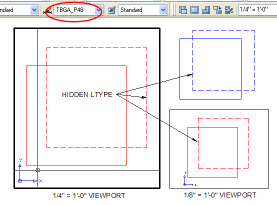
The result is a Viewport from an Arc. Friends, one ought not be allowed to do this! You cannot select an Arc to convert to a Viewport, so why should AutoCAD allow you to trim a Circle bound to a Viewport? That's just asking for trouble.

A Bonus exercise for the reader: see if you can figure out how to achieve this Viewport:
This is a single viewport with a circular void in it; see how the crosshairs pass behind the circular region?

Wednesday, August 23, 2006

The Layer Translator

Change AutoCAD drawing layers from one standard to another using the Layer Translator. This former Express Tool has been added to the standard AutoCAD toolset.

Pull down menu: Tools > CAD Standards > Layer Translator...
Command: LAYTRANS

The Layer Translator dialog lists the Layers of the current drawing in the Left pane. The right pane lists the target Layers. You populate the right pane by loading Layers from an existing drawing, template, or drawing standards file. You can also add new Layers on the fly using the "New..." button.

In the left pane select a Layer to translate, in the right pane select a Layer to translate to, and click the "Map" button; a Layer Translation Mapping list is created in the lower pane. Multiple Layers can be mapped to the same target Layer. This mapping is then applied with the "Translate" button, and/or saved to a drawing standards file (DWS) with the "Save" button. Layer Mappings loaded from a DWS automatically populate the Layer Translation Mappings pane.

Translated Layers take on the properties of the destination Layer. Mapped Layers are removed from the current drawing. The "Map same" button can be used to map all current Layers to Layers of the same name, effectively changing their properties to match the target Layer properties.

The "Settings..." button gives you even more control over Layer translation.

The default settings allow you to change the properties of objects on a Layer to Color ByLayer and Linetype ByLayer during translation. Objects nested within blocks are also translated.

You can cause the Layer Translator to display the contents of each Layer as you're remapping (similar to the old Layer Walk Express Tool).

Tuesday, August 15, 2006

Using Scripts to Automate Layer settings

Scripts are used to automate repetitive tasks in AutoCAD. A good example for this would be modifying layer settings.

If you can type it, you can Script it. This means that you'll need to become familiar with the command line versions of several AutoCAD commands. To run the command line version of a dialog driven command, like LAYER, you prefix the command with a dash: -LAYER

So here's a typical scenario: You attach an architectural floor plan background to your drawing. Now you want to set all or some of the layers to a screened Color or Plot Style. You also want to Freeze all the architectural background Layers except those germane to your discipline. If the architect later adds a Layer to their background, and it now inconveniently shows up in your drawing, you can simply rerun the Script to Freeze it, restoring your drawing to the desired display state.

Use Notepad (or your favorite text editor) to create the Script ALAY.SCR; it must have the extension .SCR to be recognized as an AutoCAD Script. Enter the following lines (or similar):

LAYER C 51
*|A-*
C 2
*|A-AREA-IDEN
F
*|A-*
T
*|A-AREA-IDEN*,*|A-DOOR-*,*|A-WALL-FULL*,etc.

Let's look at the Script line by line.

  • Line 1 executes the Layer command, specifies the Color option and selects Color 51.
  • Line 2 uses wildcards to apply Color 51 to all Layers that are both Xref dependent (includes a "|") and start with A-.
  • Lines 3 and 4 similarly reset the Room Number Layer to Color 2.
  • Lines 5 and 6 Freeze all Xref Layers that begin with A-.
  • The last two lines then Thaw all the Layers we want to display in our background, using wildcards where appropriate.

Some notes on our script:

  • Execute the Script by typing SCRIPT and selecting ALAY.SCR from the Open dialog, or drag-and-drop the Script from Explorer, or put the Script on a Tool Palette.
  • Notice that I didn't use -LAYER in the script; AutoCAD is smart enough to use the command line version of commands when called from a Script.
  • Wildcards can be asterisks or question marks. Asterisks match multiple characters and question marks match a single character.
  • Spaces act as enters in Scripts (similar to how they do at the command line), except where AutoCAD expects text entry then spaces are allowed (as in Layer names). That's why our Layer name entries are all on separate lines.
  • The Layer command needs an additional Enter to exit the command, so be sure to include an extra blank line at the bottom of your Script.

Tuesday, August 08, 2006

Hyperlinks 404

You can attach hyperlinks to graphic objects in your AutoCAD drawing. Hyperlinks are accessed by hovering over an entity; a hyperlink icon is displayed. Now, either Ctrl-Click to follow the link, or select the object, right-click, and select Hyperlink from the menu.

Hyperlinks can be links to websites (URLs). They can be email links. They can also be links to external files.

To add a hyperlink to an entity: select the entity, then either press Ctrl-K, or click on the Insert menu and choose Insert Hyperlink.


Enter the URL, email address, or file name. You can also select from Recent Files, previously Browsed Pages, or previously Inserted Links. You can set the Target location to take you to a named View in the current or linked (target) drawing. In the example above, a hyperlink is added to the column bubbles and linked to an external text file that has relevant notes regarding the grid for the project.

Another use of hyperlinks is adding "tool tips" to entities. For example add a hyperlink to a column line. Type the Column Number for the web page name. Now, when you hover over the column line, its designation appears like a tool tip so that, even if the column bubble designation is not visible on the screen, you still know which column you're working with.

Tuesday, August 01, 2006

Toggling TILEMODE

To switch between Paper Space and Model Space, AutoCAD expects you to toggle the value of TILEMODE, either by entering TILEMODE at the command line and changing its value (0=OFF, 1=ON), or clicking on the Model/Layout tabs at the bottom of the drawing editor.

The downside to both of these methods is that AutoCAD does nothing to handle Linetype Scaling.

Why is resetting LTSCALE important?

If you toggle TILEMODE without accounting for LTSCALE, either your linetypes will fail to display in Paper Space because they're too large, or they'll be far too small and generate many times more segments than are needed for Model Space. This can drastically impact performance by using up a significant amount of your resources just to hold the display list.

When PSLTSCALE is 1 (On), Paper Space Viewports automatically apply the inverse of the Viewport Zoom scale factor (times the LTSCALE) as the linetype scale for entities in that Viewport.

You can create a menu button for changing Paper/Model Space that not only toggles TILEMODE but resets the LTSCALE and PSLTSCALE beforehand. Your AutoLISP code for this button might look something like this:
(if (zerop (getvar "TILEMODE"))
(progn
(initget 7)
(setvar "LTSCALE" (getint "\nLTSCALE: "))
(setvar "TILEMODE" 1))
(progn
(setvar "LTSCALE" 1)
(setvar "PSLTSCALE" 1)
(setvar "TILEMODE" 0)))
This code snippet checks the current value of TILEMODE. If it's 0 (zero) it means you're currently in Paper Space so it prompts you for a target LTSCALE value, then toggles to Model Space. If TILEMODE is not 0 (zero) you're in Model Space, so it sets LTSCALE to 1, enables Paper Space linetype scaling, then toggles to Paper Space.

(You could add additional program code to try to divine the target LTSCALE for you rather than stopping to prompt you, but that's more than I want to get into in this post.)


In the image above TILEMODE=0 (Paper Space) with PSLTSCALE=1 and LTSCALE=1; the linetypes for entities in the scaled Viewports and the entities in Paper Space all display correctly.