Wednesday, April 25, 2007

Globally Import Page Setups

I'm often asked... sometimes asked... well, somebody asked me once if there was a way to globally import page setups into multiple drawings.

If you're using Publish you can apply page setup overrides at plot time to all sheets, even sheets that do not contain, or have incorrect page setups. But, you're obsessive compulsive conscientious and you want all of your sheets to contain the correct Named Page Setups. Use DWG TrueView 2008 (or previous versions of DWG TrueConvert) to globally apply Named Page Setups to existing sheets.

DWG TrueView is a free download from Autodesk to view, plot, and convert DWGs from one AutoCAD format to another.

Start the application with: Start > All Programs > Autodesk > DWG TrueView 2008> DWG TrueView 2008
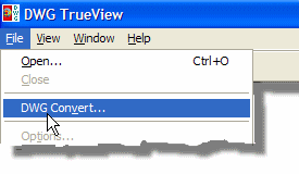
To import page setups:

  • File > DWG Convert... to open the DWG Convert module. Here you will add the files into which you wish to import the new page setups. At this point you're probably asking yourself "Why am I converting files? I don't want to convert the file format." Bear with me, there's a little trick coming.
  • Click the Conversion Setup... button and create a New conversion setup. Name it Import Page Setups with the following settings:
  • Conversion package type: In-place (overwrite files)
  • File Format: (and this is important!) This must match the current drawings' version or you will in fact convert your drawings.
  • Check the Create backup files toggle if you want to make BAKs of the DWGs, (not a bad idea).
  • And here's the trick: check the Replace page setups toggle. Use the Page Setups... button to browse to the drawing or template that has the new and improved page setups. Select the desired page setups to import, and click OK (twice) then Close to return to the DWG Convert dialog.
  • Use the add the drawings button (at the bottom of the file list) to add the sheets that are to receive the new or modified page setups.
  • Make sure that your new conversion setup is highlighted and click the Convert button.

There are some significant caveats to keep in mind using this method:

  • This method replaces all page setups in the target drawings. Existing page setups are removed and the new ones are imported.
  • This method does not set a page setup as current. The previous (and now missing) page setup is still current, even if it has the same name as an imported page setup. So you still have to go through each drawing and set an imported Named Page Setup as current (sigh). BTW I have an AutoLISP routine that will set as current a Named Page Setup. This lisp code can be run in a global script to fix each drawing.

Friday, April 13, 2007

Introducing Autodesk Design Review 2008

You may have previously known this application as DWF Composer. It has recently undergone significant transformations:
  • It's now FREE from Autodesk. Finally!
  • It can batch print multiple, individual DWF files (with a plug-in, also free).
  • It can now import DWG and DXF files, even DGNs (with free plug-in).
  • It can write Microsoft compatible DWFx files. (for Windows Vista's XPS Viewer.)

Autodesk Design Review allows you to:

  • View DWF files.
  • Redline DWF files (these markups can be later viewed by AutoCAD in the original drawing).
  • Measure distances and areas.
  • Print to scale, cropping or tiling the drawing as necessary.

You can install Design Review by downloading it from the Autodesk website.

Use Start > Programs > Autodesk > Autodesk Design Review to launch the application.

  • Open a DWF with File > Open
  • Import a DWG with File > Import (Unfortunately, Design Review doesn't understand Xrefs, so this has limited usefulness.)
  • The Contents pane of the Navigator (at left) allows you to view the desired page of your DWF file.
  • Zoom and Pan using the wheel on your wheel mouse. Roll up and down to Zoom in and out. Pick and hold the wheel to Pan the view.
  • Redline by placing call outs, drawing freehand, or placing stamps using the markup tools on the toolbar.
  • The measuring commands on the toolbar allow you to trace geometry for distances and areas.
  • Redlines and Dimensions are listed in the Markups pane, allowing you to Jump to or delete the markup.
  • Turn On/Off layers (if they were saved in the DWF) using the Layers pane.
  • Compose your DWFs combining multiple DWFs into a single, multi-page file, or remove or reorder pages within your DWF file.

This is just a brief overview of the functionality available in Design Review. Now, some things to know about AutoCAD:

  • The easiest way to save Layer information in your DWFs is through the PUBLISH command under the Publish Options; or you can do it with the PLOT command by changing the properties of the DWF6 ePlot.pc3.
  • View redline DWFs using the MARKUP command; File > Load Markup Set

Bonus tip: Show your project managers how to use this tool. Give them DWFs to view and redline thus keeping them safely out of AutoCAD and your valuable DWGs!

Quick Select

Quick Select allows you to use criteria for selecting objects. For instance you want to select all blocks of a given name:

Open your Properties palette by clicking the Properties button on the Standard Toolbar (or Modify > Properties, or Ctrl+1, or PROPERTIES at the command line). Click the Quick Select button in the upper right corner of the Properties palette.

This brings up the Quick Select dialog. Work this dialog from the top down.
  • Apply the selection criteria to the Entire drawing, or limit it to a specific area or selection set by clicking on the Select objects button at the right.
  • Set the Object type to Block Reference.
  • The Property to select by is Name.
  • The Operator to use is Equals. Set the Value to the desired Block name, e.g. EP-502.
Click OK and AutoCAD, in this example, selects all Blocks in the current space whose Name equals EP-502.


This information is now displayed in the Properties palette.

Now you can do something against this selection set. Say you want to change the scale of all of these block symbols from 72 to 96. Notice the X, Y, and Z scales of the currently selected blocks; the Y scale varies. This probably means that some of the Blocks were Mirrored and the Y scale is negative. If we simply change the scale to 96 for all three scales, we would "flip" the mirrored Blocks.

So, we first need to refine our selection set. Click the Quick Select button again.

This time:

  • Apply criteria to the Current selection to further modify it.
  • Leave the Object type as Block Reference.
  • Change the selection Property to Scale Y.
  • Use Great than as the Operator.
  • and enter 0 for the Value.

Click OK and examine the results in the Properties palette.

There should be fewer selected blocks (only blocks with positive Y Scales) and the Scale Y will (hopefully) now read the same as the X and Z scales. Change these values to 96 to rescale your Blocks: X=96, Y=96, and Z=96.

Perform these operations again, using a Less than operator this time, to rescale the mirrored Blocks as well: X=96, Y=-96, and Z=96.

Use Quick Select to apply all manner of criteria to your selections.