Wednesday, June 28, 2006

Cycling Among Open Drawings

Many of the users at work use a third party application such as Tony Tanzillo's AcadXTabs, or CADWerx's DocBar, to manage open drawings. These apps create a tabbed list of open drawings making it easy to switch between them by clicking a named tab.
These applications are no longer freeware. They have become popular enough that the authors are charging for their use and maintenance. The last free versions available will continue to operate in AutoCAD versions from 2000 to 2006. There is not a freeware version of these apps available for AutoCAD 2007. At this time I do not know of another free solution. (Does anyone know of such a program?) If you've grown too dependant on these apps to lose them, you're going to have to convince your local management to purchase a seat for your workstation.

There are alternative methods for cycling among open drawings. Perhaps one of these methods will satisfy your needs:

TASKBAR

The TASKBAR system variable can set to 1 (on) which causes each open drawing to appear as a button on the task bar. The default condition is 0 (off) where only the current drawing is shown on the task bar. The button sizes vary depending on the number of open drawings, the height or position of the task bar, and whether the "Group similar task bar buttons" options is on or off in the task bar properties. Enabling TASKBAR allows you to use Alt+Tab to cycle among open drawings.

Ctrl-Tab

This key combination cycles through open drawings. Ctrl-Shift-Tab reverses the cycle direction. You can also use Ctrl+F6 and Ctrl+Shift+F6.

Alt-W

With the ACAD menu loaded, this key combination activates the Window menu pull down, (just as if you had clicked on it). The open drawings are listed, and can be selected from the bottom of this pull down.
Wednesday, June 21, 2006

Trim/Extend

Did you know that the TRIM and EXTEND commands are just two faces of the same coin? This tip examines some of the aspects of these two-faced commands.

Flip-flop

When using Trim, hold down the Shift key and you're in Extend mode; the current Cutting edges temporarily become Boundary edges. The converse is also true: in Extend, hold down Shift to Trim.

Too Many Edges

If you simply hit Enter when prompted to select Cutting or Boundary edges, ALL entities become edges, even entities within Blocks and Xrefs.

Over the Edge

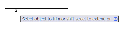
The Edge mode allows you to Trim/Extend to implied edges. Implied edges are boundaries that would intersect your entities if the boundaries were long enough.

Command: TRIM
Current settings: Projection=UCS, Edge=None
Select cutting edges ...
Select objects or <select all>: [select vertical line]
Select object to trim or shift-select to extend or
[Fence/Crossing/Project/Edge/eRase/Undo]: E
Enter an implied edge extension mode [Extend/No extend]
<No extend>: E
Select object to trim or shift-select to extend or
[Fence/Crossing/Project/Edge/eRase/Undo]:
[select horizontal lines]


in the example above, Trimming/Extending the horizontal lines to the vertical boundary with Edge mode set to Extend yields the following result:

The edge mode is stored in the EDGEMODE system variable.
"I'm not a doctor, but I play one on TV..."

There's also a Projection mode to control how trimming and extending behaves with 3D entities that don't actually intersect, but appear to intersect, in various projections.

The setting for the projection mode is stored in the system variable PROJMODE and has the following values:

0 - True 3D mode (no projection)
1 - Project to the XY plane of the current UCS
2 - Project to the current view plane

Tuesday, June 13, 2006

Control Mtext Line Spacing

Have you ever placed two Mtext entities and noticed that one has a different line spacing than the other? Or have you converted Text to Mtext and the line spacing changed? This tip is all about controlling line spacing in Mtext.

What controls the line spacing? For Dtext, the line space is defined within the font. For Mtext, the font definition is ignored, and AutoCAD uses the 5/3rds rule for spacing; this means that the spacing between text baselines is 5/3rds the height of the text.
By default the MTEXT command uses the line space setting "At least" to apply the 5/3 rule to the total height of the text; this includes ascenders and descenders that reach above the character height and below the text baseline. You can use the "Exactly" setting to ignore the ascenders and descenders, applying the 5/3 rule to only the base character height. In the example above, the left Mtext uses the default setting of "At least" and the right uses "Exactly." Note how the left Mtext's line spacing starts to increase on the third line, which contains backslashes, and again on the last line with the apostrophe.

To change the default Mtext line spacing, start the MTEXT command, select your start point for the Mtext bounding box, but before picking the other corner, issue the "Line spacing" option:

Command: MTEXT
MTEXT Current text style: "Standard" Text height: 1
Specify first corner: [pick a point]
Specify opposite corner or [Height/Justify/Line spacing/Rotation/Style/Width]: L
Enter line spacing type [At least/Exactly] <At least>: E
Enter line spacing factor or distance <1x>: [enter]
Specify opposite corner or [Height/Justify/Line spacing/Rotation/Style/Width]: [pick other corner]

Once set, this value stays set and doesn't need to be set again. It is stored in the TSPACETYPE system variable.

You can also modify existing Mtext's spacing type using the Properties palette and changing the "Line space style."

If you must have Mtext line spacing match Dtext line spacing, you can accomplish this with the "line spacing factor or distance" in the Mtext options (see prompts above). This value is stored in the TSPACEFAC system variable, which defaults to 1 and is not saved in the drawing or registry.

Tuesday, June 06, 2006

Zoom to Objects

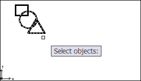
Another command prompt option snuck into the ZOOM command in AutoCAD 2006. The Object option allows you to zoom up on selected objects.

Command: ZOOM
Specify corner of window, enter a scale factor (nX or nXP), or
[All/Center/Dynamic/Extents/Previous/Scale/Window/Object] <real>: O
Select objects:

ZOOM Object with two entities selected

Display after ZOOM Object

AutoCAD resizes the display to "fit" the selected entities.

Thursday, June 01, 2006

Change the Block Insertion Point on the Fly

How often do you read your AutoCAD prompts? The Basepoint option is a little gem that snuck into the AutoCAD 2006 INSERT command. This option allows you to override the Block's insertion point with a base point of your own while you're placing the block.

Command: INSERT
Enter block name or [?] : [block name here, or from dialog]
Specify insertion point or [Basepoint/Scale/Rotate/PScale/PRotate]: B
Specify base point: [pick new base point]
Specify insertion point: [place the block]


Note: You only get the "Specify insertion point:" prompt if you tell the insertion dialog to specify insertion point "On-screen".

Once you've placed the block, highlight it. Notice that you haven't changed the actual insertion point; the base point override was only for the initial placement.

The other options available at the insertion point prompt have been there for some time, but are still pretty cool. You can set the Scale and Rotation before placing the block. This allows you to drag the block at the new scale and rotation, which can be helpful in visualizing its placement. You won't be prompted again for these values once you pick the insertion point. If you want to be prompted again, use the PScale or PRotation options instead.